2SA835 / 2SC1663
1. Overview
The 2SA835 (PNP) and 2SC1663 (NPN) are a complementary pair of transistors manufactured by SONY for audio amplifier applications. According to SONY’s databook, they are characterized as suitable for 30W-class Class-B driver stages.
During the 1970s and 1980s, SONY was actively developing discrete semiconductors for audio use. The 2SA835/2SC1663 were adopted in the company’s audio equipment such as the TA-5650 — representative examples of that golden era.
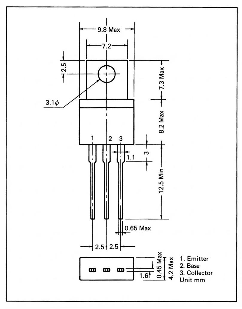
The TO-202N package has a distinctive shape. While mounting it to a heatsink requires dedicated hardware, the package itself features a small integral heat-dissipation fin, making it usable without an additional heatsink at low current levels.
Today, a small-power transistor rated below 1W collector dissipation would likely be released in a plastic-molded TO-92MOD package.
Back then, however, transistors developed for audio applications often employed packages with superior thermal characteristics for the sake of sound quality — a clear distinction from their modern counterparts.
1.1 Application Example: SONY TA-5650
The SONY TA-5650 (1970s) is a legendary power amplifier from SONY’s audio golden era, featuring the renowned V-FET (2SJ18/2SK60) in its output stage. The 2SA835/2SC1663 are used in the driver stage in an inverted Darlington (Sziklai Pair) configuration.
The reason SONY chose the 2SA835/2SC1663 for the TA-5650 is likely that during their golden era, SONY insisted on using in-house transistors throughout their designs. For detailed circuit analysis, see “4.5 Restoration Notes“.
1.2 The Era of SONY Transistors
SONY once developed their own bipolar transistors and small-signal FETs specifically for their audio and video equipment. The 2SA835/2SC1663 were part of this effort.
By the early 1980s, however, SONY had scaled back external sales of bipolar devices, and through the 1990s, their FET lineup also gradually faded away.
Looking at the 1988 SONY Discrete Semiconductor Data Book, JFETs such as the 2SK125 and dual-gate MOSFETs like the 3SK165 are still listed as active products, but there is no mention whatsoever of audio bipolar transistors including the 2SA835/2SC1663.
It is highly likely that SONY had wound down bipolar transistor production by 1988.
Today, SONY Semiconductor focuses on image sensors, and their vintage discrete devices are only available as NOS (New Old Stock). A more detailed history of SONY semiconductors will be covered in a separate article.
1.3 Availability of SONY Transistors
SONY transistors were never particularly easy for hobbyists like us to obtain.
During the audio boom of the 1970s, some electronics parts shops in Tokyo’s Akihabara district did carry them, and in later years NOS (New Old Stock) units could occasionally be found as remnants of that era.
As of 2025, however, even NOS stock is becoming increasingly difficult to find. The rise of online distributors like Mouser and Digi-Key has driven brick-and-mortar electronics shops toward extinction.
There was always the thrill of stumbling upon hidden treasures at physical shops… but that’s a story for another time.
2. Catalog Information
2.1 Features
- AF/HF power amplifier and high-voltage switching applications
- High breakdown voltage: Vceo = 140V
- Medium power: Pc = 0.95W
- High DC current gain: hFE = 60–350
- TO-202N package with integral heat-dissipation fin
Source: SONY Semiconductor Handbook 1979
2.2 Related Devices
The databook pages for the 2SA835 and 2SC1663 also briefly mention the following related devices:
- 2SA951: A pinout variant of the 2SA835 (collector-center type: B-C-E from left when viewed from the marking side)
- 2SC1962: A higher-voltage version of the 2SC1663 (Vcbo & Vceo = 200V)
Source: SONY Semiconductor Handbook 1979
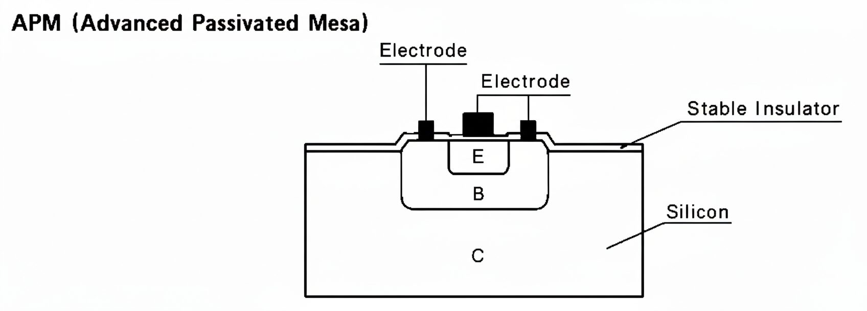
2.3 Difference in Fabrication Process
Interestingly, despite being a complementary pair, the two devices use different fabrication processes:
- 2SA835: SEP (Stable Epitaxial Passivated) — essentially an epitaxial planar structure. The surface passivation film incorporates various stabilization treatments as needed.
- 2SC1663: APM (Advanced Passivated Mesa) — a mesa structure with a stabilized insulating passivation layer.
This difference may be one factor contributing to the differing hFE-Ic characteristics between the PNP and NPN devices (discussed later).
2.4 Absolute Maximum Ratings (Ta=25°C)
| Parameter | 2SA835 | 2SC1663 |
|---|---|---|
| Process | Si SEP | Si APM |
| Vcbo (V) | -140 | 140 |
| Vceo (V) | -140 | 140 |
| Vebo (V) | -8 | 8 |
| Ic (A) | -0.5 | 0.5 |
| Pc (W) | 0.95 | 0.95 |
Source: SONY Semiconductor Handbook 1979
2.5 Electrical Characteristics (Ta=25°C)
| Parameter | 2SA835 | 2SC1663 |
|---|---|---|
| hFE (hFE1)Ic=±0.1A, Vce=±2V | Min.60 Typ.150 Max.350 |
Min.60 Typ.150 Max.350 |
| hFE2/hFE1hFE2: Ic=±0.5A, Vce=±5V | Min. 0.5 | Min. 0.5 |
| Vcesat (V)Ic=±1A, Ib=±0.2A | Max. -0.7 | Max. 0.7 |
| fT (MHz)Ic=±0.02A, Vce=±10V | Min.30 Typ.45 |
Min.30 Typ.50 |
| Cob (pF)Vcb=±10V | Typ.30 Max.40 |
Typ.15 Max.20 |
Source: SONY Semiconductor Handbook 1979
No hFE rank classification was described in the databook.
3. Product History
3.1 Product History Timeline (SONY & CQ Publishing Sources)
Since original SONY transistor databooks are extremely difficult to obtain today, CQ Publishing’s “Transistor Specification Tables” (最新トランジスタ規格表) and “Transistor Replacement Tables” (最新トランジスタ互換表) were also referenced to trace the timeline as far as possible.
* For more on “CQ Publishing”, see Reference Materials.
| Year | 2SA835 | 2SC1663 |
|---|---|---|
| 1976 | — | Production started |
| 1977 | Production started | — |
| 1981 | Derivatives introduced (-101, -RED) | — |
| 1984 | Designated as maintenance part | Designated as discontinued |
| 1986 | Maintenance part (status continued) | — |
| 1987 | Details unknown (*) | — |
| 1988 | Not listed in databook | Not listed in databook |
Sources: SONY Semiconductor Replacement Handbook (ソニー補修用半導体ハンドブック) 1981/1982/1994, 1988/1992 Sony Discrete Semiconductor Data Book, CQ Publishing “Transistor Replacement Tables” (最新トランジスタ互換表) 1971–2005
* From 1987 onward, CQ Replacement Tables no longer distinguished between “maintenance” and “discontinued” parts — details unknown.
See “5.2 The 1987 Problem in CQ Replacement Tables” for details.
As discussed in “1.2 The Era of SONY Transistors“, it is highly likely that SONY had wound down bipolar transistor production by 1988.
3.2 Derivative List
| Part Number | Package | Year Documented | Notes |
|---|---|---|---|
| 2SA835 | TO-202N | 1979 | Original |
| 2SA835-101 | TO-202N | 1981/1982 | Derivative |
| 2SA835-RED | TO-202N | 1981/1982/1994 | Derivative |
| 2SA835-10 | TO-202N | 1994 | Derivative |
| 2SA835 (late production) | TO-220 | 1994 | Derivative (package & rating changed) |
| 2SC1663 | TO-202N | 1979 | Original |
Sources: SONY Semiconductor Handbook 1979, SONY Semiconductor Replacement Handbook 1981/1982/1994
3.3 Discussion on Derivatives
3.3.1 The “SONY Semiconductor Replacement Handbook” and 2SA835 Derivatives
The 2SA835 has derivative versions — 2SA835-101, 2SA835-RED, and 2SA835-10 — that are not listed in the 1979 SONY Handbook (which this site owns).
The existence of these derivatives can be confirmed through the “SONY Semiconductor Replacement Handbook” (ソニー補修用半導体ハンドブック). The preface of this handbook states (translated from the original Japanese):
This handbook consists of technical memos, replacement tables, specification summaries, and outline dimension drawings. It is compiled primarily to address semiconductor replacement needs during service repairs, covering transistors, diodes, and ICs used in SONY products.
Replacement compatibility is determined based on absolute maximum ratings, electrical characteristics, and package form. However, depending on the specific equipment, there may be safety designations, tight specification subdivisions, or combination-dependent adjustments required. Please refer to the original equipment’s service guide for details.
Please use in conjunction with CQ Publishing’s “Transistor Specification Tables” (トランジスター規格表), “Diode Specification Tables” (ダイオード規格表), and “Transistor Replacement Tables” (トランジスター互換表).
Fortunately, this site owns the 1981/1982/1994 editions of this handbook. The information obtained regarding 2SA835/2SC1663 is shown below.
| Edition Year | Type No. | Replacement | Vceo (V) | Package | Notes |
|---|---|---|---|---|---|
| 1981/1982 | 2SA835 | 2SA835 | -200 | TO-202N | |
| 2SA835-101 | 2SA835-101, 2SA835-RED | Not specified | TO-202N | Used in audio products | |
| 2SA835-RED | 2SA835-101, 2SA835-RED | Not specified | TO-202N | Used in audio products | |
| 2SC1663 | 2SC1962 | 140 | TO-202N | ||
| 1994 | 2SA835 | Not specified | -200 | TO-220 | |
| 2SA835-RED | 2SA835-10 | -140 | TO-202N | Used in audio products | |
| 2SA835-10 | 2SA835-10 | Not specified | Not specified | ||
| 2SC1663 | 2SC1962 | 140 | TO-202N |
Source: SONY Semiconductor Replacement Handbook 1981/1982/1994
It appears that the 2SA835-101 and 2SA835-RED may have been screened/selected parts specifically for audio products, but the replacement handbook offers no further detail, and the specifics remain unknown.
Regarding the 2SA835-101 and 2SA835-RED, each edition of the handbook includes the following visual identification diagram:
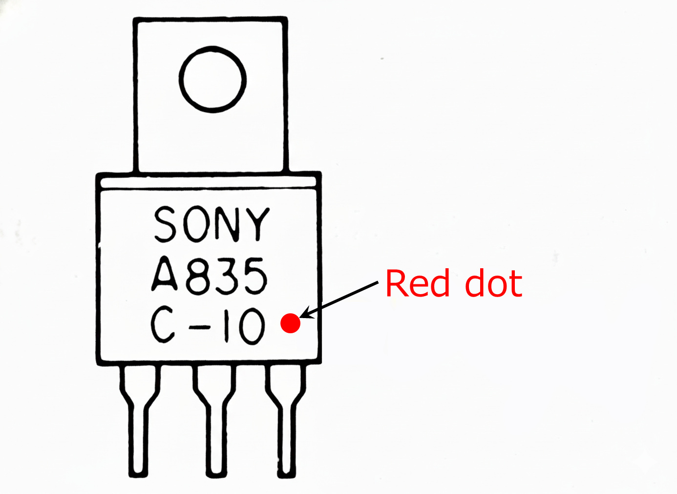
As this shows, SONY transistors may have different absolute maximum ratings (critical information) depending on the suffix letters or numbers following the part number, so caution is required.
3.3.2 The Mystery: Why Only the PNP Was Repackaged to TO-220
According to CQ sources, the 2SA835/2SC1663 were designated as maintenance/discontinued in 1984. Notably, however, the 2SA835 was still described as a “maintenance part” in the 1985/1986 editions.
This suggests that the 2SA835 may have remained in production until at least 1986.
(Unfortunately, from 1987 onward, CQ Replacement Tables abolished the distinction between “maintenance” and “discontinued,” marking both simply as “maintenance/discontinued.” Additionally, from 1989 onward, CQ Specification Tables stopped listing data for parts already designated as maintenance/discontinued by 1988, making it even more difficult to estimate the exact production end date.)
Further supporting this, a comparison of the 1982 and 1994 SONY Semiconductor Replacement Handbooks reveals that the 2SA835’s package was changed from TO-202N to TO-220, and its maximum ratings were upgraded (Vceo: 140V → 200V).
The situation is further complicated by the fact that the related device 2SA951 (a pinout variant) had already been repackaged from TO-202N to TO-220 as early as 1981 — earlier than the 2SA835.
Let us now compile a comprehensive timeline including the related devices, based on CQ sources.
| 75 | 76 | 77 | 78 | 79 | 80 | 81 | 82 | 83 | 84 | 85 | 86 | 87 | 88 | 89 | 90 | 91 | 92 | 93 | 94 | |
|---|---|---|---|---|---|---|---|---|---|---|---|---|---|---|---|---|---|---|---|---|
| 2SA835 | — | — | ■ | ■ | ■ | ■ | ■ | ■ | ■ | □ | □ | □ | ||||||||
| 2SA951 | — | — | ■ | ■ | ■ | □ | □ | □ | ||||||||||||
| 2SC1663 | — | — | ■ | ■ | ■ | ■ | ■ | ■ | ■ | ✗ | ✗ | ✗ | ✗ | ✗ | ✗ | ✗ | ✗ | ✗ | ✗ | ✗ |
| 2SC1962 | — | — | — | ■ | ■ | ■ | ■ | ■ | ■ | □ | □ | □ |
(Legend) —: Before introduction, ■: In production, □: Maintenance part (保守品種, roughly comparable to NRND: production continued for existing designs only), ✗: Discontinued (廃品種: production ceased), blank: Unknown
3.3.3 Analysis: Why Did Only the PNP Survive in a New Form?
The timeline table makes it clear that the PNP devices — 2SA835 and 2SA951 — along with the NPN 2SC1962 (the higher-voltage version of 2SC1663, i.e. its upward-compatible replacement) remained in production for some time as service parts.
Why did the 2SA835 and 2SA951 continue production in a modified form? What follows is purely speculative, but…
During their audio golden era, SONY actively used in-house transistors. But around the time V-FET amplifier sales ended circa 1980, the company gradually shifted toward using third-party transistors.
The 2SA835/2SC1663, which had also been used as V-FET driver transistors, were slated for phase-out. However, it is said that under guidance from Japan’s MITI (now METI), audio product manufacturers were expected to supply replacement parts for approximately 8 years after production ended. Thus, spot production continued. During this period, the 2SC1663 was rationalized by consolidating production into the upward-compatible 2SC1962.
Meanwhile, the 2SA835 and 2SA951 were also used in power supply circuits and other blocks requiring PNP devices in professional audio equipment. Since professional equipment has a long service life with ongoing demand for new units before model changes, continuous production was necessary.
In other words, PNP demand persisted not just for replacement parts but for new production. This may be why SONY transitioned to a new manufacturing line using the more versatile TO-220 package. At least, that is this author’s theory.
3.3.4 About the SONY Semiconductor Replacement Handbook
What makes the Replacement Handbook particularly interesting is that it provides individualized replacement information not just for SONY’s own derivatives, but also for third-party parts — distinguishing every rank classification separately.
Take, for example, the world-famous 2SC1815. In the 1994 edition, SONY provides the following replacement information:
| Type name | Replacement |
|---|---|
| 2SC1815-BL | 2SC1815-BL★ |
| 2SC1815-GR | 2SC1815-GR★ |
| 2SC1815-O | 2SC1815-O |
| 2SC1815-Y | 2SC2785-HFE |
| 2SC1815-YGR | 2SC2785-HFE |
| 2SC1815NEW | 2SC2785-HFE |
| 2SC1815Y-TPE2 | 2SC2785-HFE |
| 2SC1815YGR-TPE2 | 2SC2785-HFE |
★: Transistors must be replaced as a pair
Source: SONY Semiconductor Replacement Handbook 1994
As shown, detailed replacement procedures are indicated with ★ marks depending on the target equipment. Moreover, the handbook distinguishes not only by hFE rank but even by packaging sub-codes (TPE: indicating taped packaging), providing optimized replacement recommendations for each variation. This is a truly invaluable resource.
4. Replacement Guide
4.1 Notes on Replacement Selection
4.1.1 About the Replacement Table
The replacement table in this chapter includes not only SONY’s own replacement information, but also general replacement data from CQ Publishing’s “Transistor Replacement Tables” and this site’s original recommendations — all consolidated in a single table.
4.1.2 Important Notes When Considering SONY Transistor Replacements
As discussed in Chapter 3, SONY transistors may have derivative versions with different absolute maximum ratings (critical information) depending on the suffix letters or numbers following the part number, so caution is required.
4.1.3 About CQ Publishing’s “Transistor Replacement Tables”
In the replacement tables published by CQ Publishing, different (non-paired) replacements are sometimes recommended for the PNP and NPN of a complementary pair like 2SA835/2SC1663.
For example, 2SC1967 (Matsushita) is recommended as a replacement for 2SC1663, but its complementary counterpart 2SA914 (Matsushita) is not listed as a replacement for 2SA835.
This suggests that the editors at the time understood that even within a complementary pair, the PNP and NPN may have subtly different fabrication processes and electrical characteristics. Rather than simply recommending another manufacturer’s complementary pair as a set, they may have intentionally selected the optimal replacement for each polarity independently.
Important: Disclaimer and Caution
The replacement information presented here is compiled based on catalog specifications from various semiconductor manufacturers and literature research. No testing on actual equipment has been performed.
Transistor replacement is an action that may cause equipment failure or performance degradation. The information on this site is provided for reference only, and this site assumes no responsibility for any damage resulting from replacement work.
Technical Considerations
When attempting a replacement, consider not only the absolute maximum ratings listed in the table (VCEO, IC, PC) but also characteristics that affect circuit behavior such as fT (transition frequency) and Cob (output capacitance). Proceed at your own judgment and risk. In particular, parts with significantly different Cob values may require phase compensation re-adjustment due to the Miller effect, potentially causing oscillation or increased distortion.
4.2 Replacement Comparison Table
Based on the notes in “4.1 Notes on Replacement Selection“, the information source for each replacement is clearly indicated in the table. Additionally, even when a source only recommends the PNP or NPN individually, both complementary pair part numbers are listed together for the reader’s convenience in evaluating replacements.
Note that a later model of the 2SA835 with upgraded breakdown voltage (Vceo=200V, TO-220) also exists. However, this table is based strictly on the 2SA835/2SC1663 (Vceo=140V) ratings and characteristics as listed in the SONY Semiconductor Handbook 1979.
★: Currently in production (as of 2025) *: Tc=25°C basis
fT & Cob columns: PNP/NPN order (single value = common to both)
Source column: CQ = CQ Publishing, SONY = SONY replacement table, Kaz = Author’s recommendation
| Part Name | Manufacturer | Package | Vceo (V) | Ic (A) | Pc (W) Ta/*Tc |
fT (MHz) | Cob (pF) | Source | Application / Notes |
|---|---|---|---|---|---|---|---|---|---|
| 2SA835 / 2SC1663 | SONY | TO-202N | 140 | 0.5 | 0.95 | 45/50 | 30/15 | — | This device |
| 2SA818 / 2SC1628 | Toshiba | TO-202N | 150 | 1 | 0.75 | 120/120 | <5/<5 | CQ | VAS (Voltage Amplification) only CQ recommends: 2SC1628 only |
| 2SA968 / 2SC2238 | Toshiba | TO-220 | 160 | 1 | *25 | 100/100 | 30/25 | CQ | Driver (100W class) |
| 2SA1837 / 2SC4793 | Toshiba | TO-220F | 230 | 1 | 2 | 70/100 | 30/20 | CQ | Driver (100W class) 2SA968/2SC2238 successor |
| 2SC1962 | SONY | TO-202N | 200 | 0.5 | 1.95 | 45 | 12 | SONY | 2SC1663 high-voltage version NPN only |
| 2SB631K / 2SD600K | Sanyo | TO-126 | 120 | 1 | 1 / *8 | 110/130 | 30/20 | CQ | Output (low power) CQ recommends: 2SB631K only Voltage rating caution |
| 2SB648 / 2SD668 | Hitachi | TO-126 | 120 | 0.05 | 1 | 140/140 | 4.5/3.5 | CQ | VAS (wideband) CQ recommends: 2SB648 only Voltage rating caution |
| 2SC1514 | Hitachi | TO-202AA | 300 | 0.1 | 1.25 | 80 | <4.0 | CQ | VAS (high voltage) TV video amp, NPN only |
| 2SA914 / 2SC1953 | Matsushita | TO-126F | 150 | 0.05 | 1 | 200/>70 | <5/<3 | CQ | VAS (wideband) CQ recommends: 2SC1953 only |
| 2SC2611 | Hitachi | TO-126 | 300 | 0.1 | 1.25 | 80 | <4.0 | CQ | VAS (high voltage) TV video amp, NPN only |
| 2SA913 / 2SC1913 | Matsushita | TO-220 | 150 | 1 | *15 | 120/120 | <15/<30 | Kaz | Driver (60–100W class) |
| 2SA985A / 2SC2275A | NEC | TO-220 | 150 | 1.5 | 1.5 / *25 | 180/200 | 29/19 | Kaz | Driver (60–120W class) |
| 2SA1006 / 2SC2336 | NEC | TO-220 | 180 | 1.5 | 1.5 / *25 | 80/95 | 45/30 | Kaz | Driver (150W class) |
| 2SA1011 / 2SC2344 | Sanyo | TO-220 | 160 | 1.5 | *25 | 100/100 | 30/23 | Kaz | Driver (100W class) |
| 2SA1111 / 2SC2591 | Matsushita | TO-220 | 150 | 1 | *20 | 200/200 | 30/20 | Kaz | Driver (100W class) |
| 2SA1112 / 2SC2592 | Matsushita | TO-220 | 180 | 1 | *20 | 200/200 | 30/20 | Kaz | Driver (120W class, high-voltage) |
| 2SA1142 / 2SC2682 | NEC | TO-126 | 180 | 0.1 | 1.2 / *8 | 180/200 | 4.5/3.2 | Kaz | Pre-driver (80–150W class) |
| 2SA1220A / 2SC2690A | NEC | TO-126 | 160 | 1.2 | 1.2 / *20 | 175/155 | 26/19 | Kaz | Driver (50–100W class) |
| 2SA1209 / 2SC2911 | Sanyo | TO-126 | 160 | 0.14 | 1.0 / *10 | 150/150 | 4.0/3.0 | Kaz | Pre-driver (100W class) |
| 2SA1249 / 2SC3117 | Sanyo | TO-126 | 160 | 1.5 | 1.0 / *10 | 120/120 | 22/— | Kaz | Driver (TV audio amp) |
| 2SA1360 / 2SC3423 | Toshiba | TO-126 | 150 | 0.05 | 1.2 / *5 | 200/200 | 2.5/1.8 | Kaz | VAS (low Cob) 2SA818/2SC1628 successor |
| 2SA1507 / 2SC3902 | Sanyo/ON | TO-126F | 160 | 1.5 | 1.5 / *10 | 120/120 | 22/14 | Kaz | Driver (TV audio amp) |
| 2SB648A / 2SD668A | Hitachi | TO-126 | 160 | 0.05 | 1 | 140/140 | 4.5/3.5 | Kaz | VAS (wideband) 2SB648/2SD668 high-voltage version |
| 2SB649A / 2SD669A | Hitachi | TO-126 | 160 | 1.5 | 1.0 / *20 | 140/140 | 27/14 | Kaz | Driver (50W class) |
| KSA1220A / KSC2690A | Fairchild | TO-126F | 160 | 1.2 | 1.2 / *20 | 175/155 | 26/19 | Kaz | Driver (50–100W class) 2SA1220A/2SC2690A compatible |
| TTA006B / TTC011B ★ | Toshiba | TO-126F | 230 | 1 | 1.5 / *10 | 70/100 | 30/20 | Kaz | Driver (100W class) 2SA1837/2SC4793 successor In production |
| TTA004B / TTC004B ★ | Toshiba | TO-126F | 160 | 1.5 | 1.5 / *10 | 100/100 | 17/12 | Kaz | Driver (100W class) In production |
Sources: CQ Publishing “Transistor Specification Tables” 1988, Toshiba Semiconductor Databook 1977/1980, NEC Electronic Device Databook ’83 Transistor Volume (電子デバイスデータブック ’83 トランジスタ編), Hitachi ’86 Transistor Data Book, Mitsubishi ’80 Semiconductor Databook Transistor & Small Signal Diode 1983–1984 (’80 半導体データブック トランジスタ 小信号ダイオード編), Matsushita ’83 National Semiconductor Discrete Devices (’83 ナショナル半導体 ディスクリート半導体), Sanyo ’87-’88 Semiconductor Databook Discrete Transistor Volume (’87-’88 半導体データブック 個別半導体素子トランジスタ編)
4.3 The Difficulty of Finding Replacements
SONY describes these as “for 30W-class Class-B driver stages,” but this classification is the result of optimization for their own amplifiers. When you line up the specs against other manufacturers’ general-purpose parts, the picture starts to look a bit different.
The 2SA835/2SC1663 specifications are, frankly, uncommon. A relatively high breakdown voltage of Vceo=140V combined with a moderate collector current of Ic=0.5A. It is surprisingly difficult to find devices with this particular combination of ratings.
For example, the 1978 CQ Transistor Replacement Table recommends Toshiba’s 2SC1628 (a similar package) as a substitute for the 2SC1663, while its complementary counterpart 2SA818 from Toshiba is not listed as a replacement for the 2SA835.
The 2SA818/2SC1628 have Vceo of 150V but only 50mA of Ic — the die size is small. In exchange, Cob is kept below 5pF. In other words, these are clearly VAS (Voltage Amplification Stage) devices.
In the 1980 edition, the Toshiba 2SA968/2SC2238 complementary pair is recommended as a direct replacement for the 2SA835/2SC1663 pair. These are optimized for driver stages with Vceo=160V and Ic=1A. In exchange, Cob is 25–30pF — considerably larger than VAS devices.
So where do the 2SA835/2SC1663 fit? Their Cob is 15–30pF. They have Vceo of 140V, but only Ic of 0.5A, in a TO-202N package that isn’t ideal for handling high power. Neither a pure VAS device nor a true driver — a rather ambiguous specification.
When selecting replacements, the most critical rule is to respect the absolute maximum ratings. Exceeding voltage-related parameters such as Vcbo or Vceo risks instantaneous destruction of the transistor.
On the other hand, exceeding the Ic maximum does not necessarily cause immediate destruction, but sustained high current will inevitably push collector dissipation beyond its limit, leading to thermal failure.
Conversely, when high voltage is applied to a transistor, even currents below the rated maximum can cause instantaneous destruction if the operating point falls outside the ASO/SOA (Safe Operating Area; ASO in Japanese convention, SOA in international convention).
Below are the ASO (Safe Operating Area) graphs for the 2SA835/2SC1663. The ASO boundary consists of three lines: a horizontal line (current limit), a diagonal line (power limit), and a vertical line (voltage limit). The region inside these boundaries is the safe operating area.
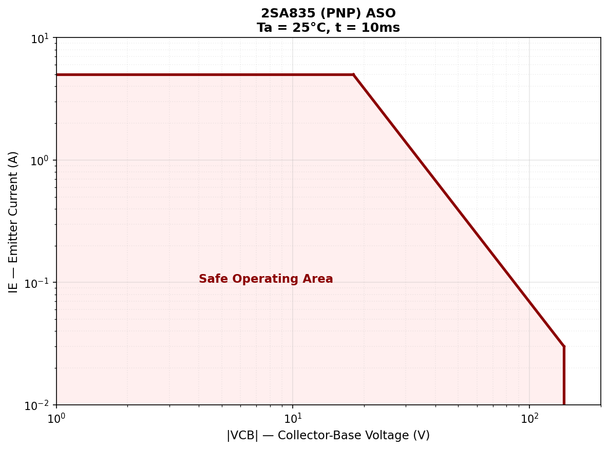
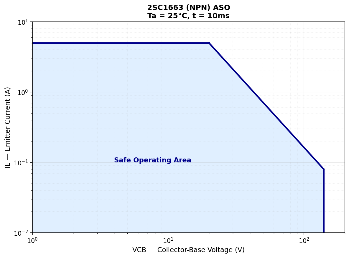
Source: Drawn by the author based on SONY Semiconductor Handbook 1979
Interestingly, despite being a complementary pair, their ASO shapes differ. The 2SA835 (PNP/SEP) allows only 30mA in the high-voltage region, while the 2SC1663 (NPN/APM) permits 80mA — more than double. This likely reflects the difference in fabrication processes.
Ultimately, judging from the Cob values, it is likely that the 2SA835/2SC1663 use a die size somewhat close to the 2SA968/2SC2238, and they are probably best suited for driver stage (complementary emitter follower) applications.
4.4 When You’re Unsure About Choosing a Replacement
If you are not confident relying solely on replacement tables, you should refer to datasheets and verify not just the package and maximum ratings, but the electrical characteristics as well.
Below, the author has plotted approximate values read by eye from the hFE vs. Ic characteristic graphs in various datasheets for potential replacement candidates.
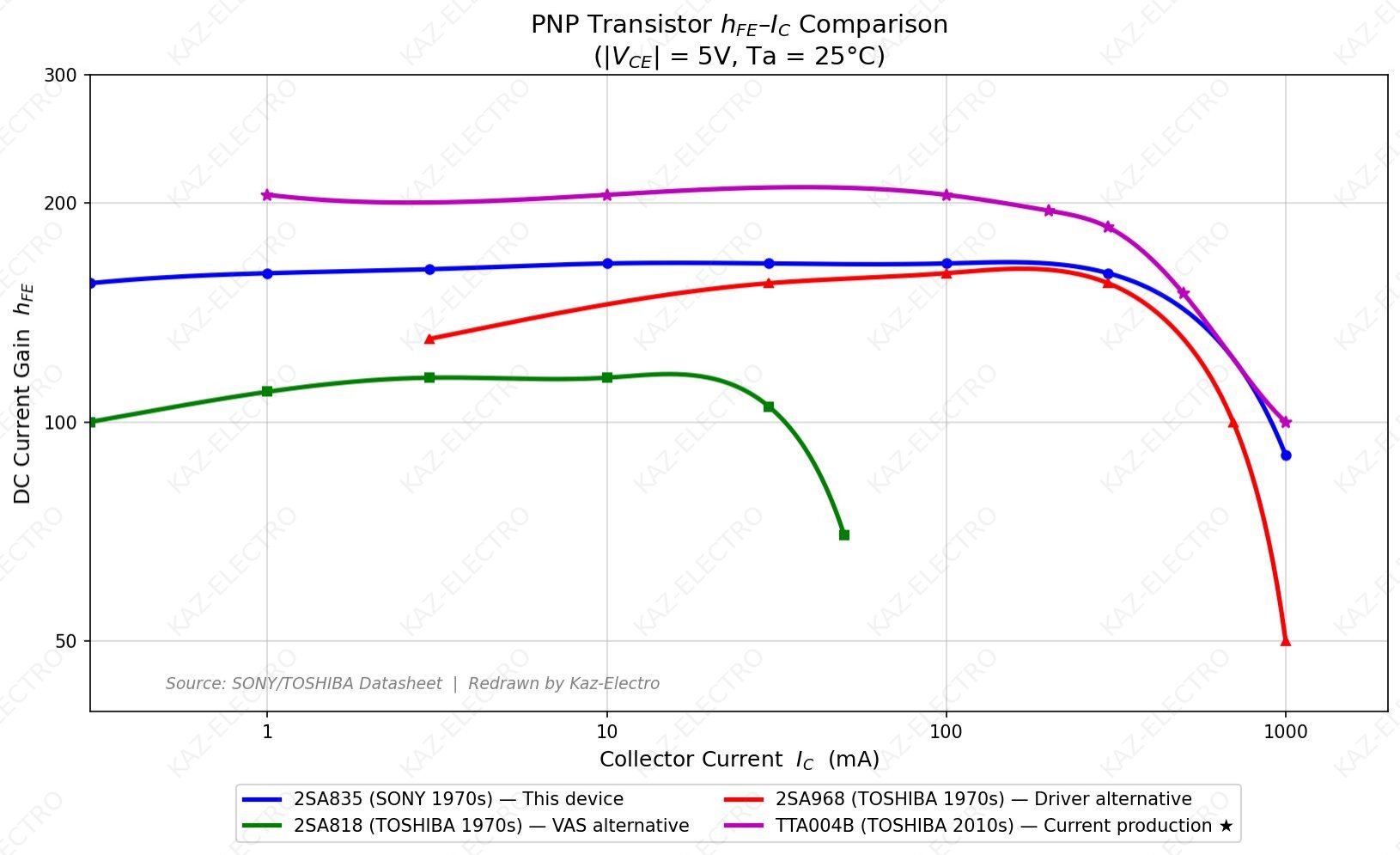
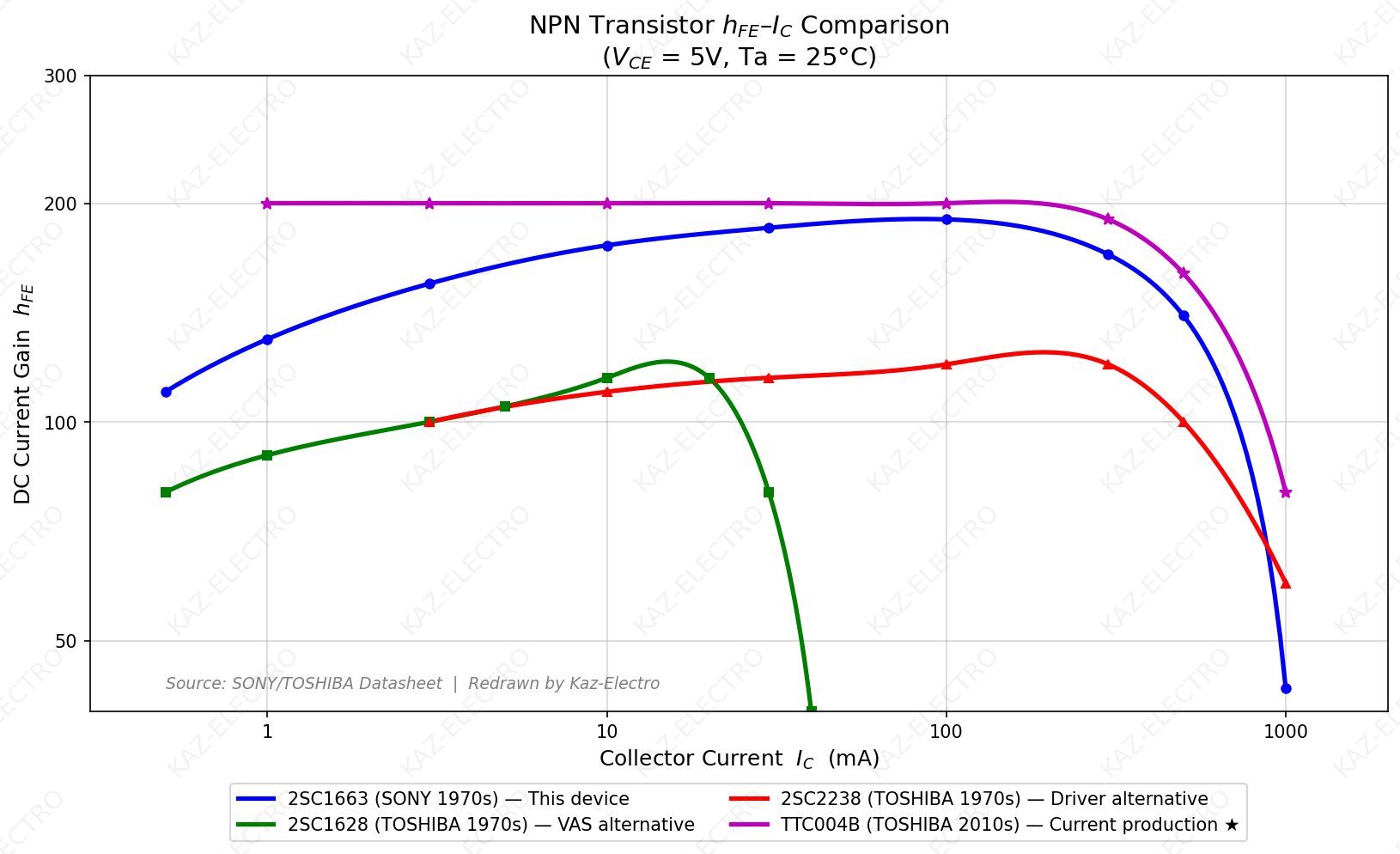
The graphs clearly show that the 2SA818/2SC1628 were developed with a focus on the 1–10mA low-current region (VAS-oriented), while the 2SA968/2SC2238 were developed for the 10–100mA mid-current region (driver-oriented).
The 2SA835/2SC1663, on the other hand, exhibit nearly constant hFE across a wide range of 3–100mA — an excellent characteristic.
What is even more interesting is that despite being a complementary pair, there is a clear difference in behavior at high currents. This may be attributable to the different fabrication processes (2SA835: SEP, 2SC1663: APM).
For reference, the Toshiba TTA004B/TTC004B, introduced in 2013 and still in production as of 2025, have also been plotted. The hFE curve behavior is relatively similar to that of the 2SA835/2SC1663. The fT and Cob values represent an improvement over the originals — both affecting high-frequency characteristics — so careful consideration is warranted; that said, availability through Mouser and Digi-Key is worth keeping in mind.
A current-production TO-126F pair. For applications in rare V-FET amplifiers such as the TA-5650, consult the datasheets thoroughly and proceed at your own judgement and risk.
4.5 Restoration Notes
4.5.1 General Guidance
If this pair is used in a VAS (Voltage Amplification Stage), the 2SA818/2SC1628 family with lower Cob and higher fT may actually be more suitable replacements. On the other hand, if used as an emitter follower in a driver stage, a 1A-class TO-220 type like the 2SA968/2SC2238 may be more appropriate.
Typical Audio Power Amplifier Configurations
- [2-stage] ≤1W: Input → Output
- [3-stage] ≤50W: Input → VAS → Output
- [4-stage] 50W+: Input → VAS → Driver → Output
VAS = Voltage Amplification Stage
Driver = Buffer stage that drives the output stage
4.5.2 Caution for V-FET Amplifier Repairs
The SONY TA-5650 introduced in “1.1 Application Example” is a legendary amplifier featuring SONY’s in-house V-FETs in the output stage. The V-FET (Vertical FET, also known as SIT) was briefly popular for its triode-like characteristics, but its difficult handling led to a short lifespan.
The 2SA835/2SC1663 are used to drive these V-FETs. The author calculated the bias current from this amplifier’s schematic to be approximately 6.7mA.
TA-5650 Driver Stage (Class B, Sziklai Pair Configuration)
- Upper: 2SC926A → 2SA835
- Lower: 2SA639S → 2SC1663
- Output: V-FET (2SJ18 / 2SK60)
⚠ V-FET Amplifier Repair Warning
When repairing V-FET amplifiers like the TA-5650, casually swapping transistors with replacements is not recommended. V-FETs (SITs) are prone to thermal runaway, and bias conditions are critical.
Furthermore, the inverted Darlington (Sziklai Pair) is a circuit topology known to be prone to oscillation. Simply substituting a part with higher maximum ratings may seem safe, but subtle differences in Cob and bias current can affect phase compensation and gain balance, potentially leading to troubleshooting nightmares or instantaneous destruction of a valuable unit.
Nearly 50 years have passed since V-FETs went extinct. Obtaining replacements is virtually hopeless. If you attempt a restoration, proceed with extreme caution.
The above may sound alarmist, but in all honesty, rough substitution with compatible parts often works well enough in practice.
That said, commercial products often feature sophisticated circuit designs. There may be sensitive circuits requiring precisely selected components, or circuits that need re-adjustment after transistor replacement. Please be fully aware that careless substitution can, in the worst case, damage the equipment or cause malfunction.
If you cannot confidently select a replacement, it may be safer to ask on forums or simply search for NOS on auction sites (but beware of counterfeits!).
If this site’s replacement table has been of any help to you, nothing would make the author happier.
5. References
5.1 Source List
- SONY Semiconductor Handbook 1979
- SONY Discrete Semiconductor Data Book 1988/1991
- SONY Semiconductor Replacement Handbook (ソニー補修用半導体ハンドブック) 1981/1982/1994
- SONY TA-5650 Service Manual
- CQ Publishing “Transistor Replacement Tables” (最新トランジスタ互換表) 1978, 1980, 1983, 1984, 1986, 1987, 1988, 1996, 2001, 2003
- CQ Publishing “Transistor Specification Tables” (最新トランジスタ規格表) 1988
- Toshiba – TOSHIBA Semiconductor Databook 1977/1980
- NEC – Electronic Device Databook ’83 Transistor Volume (電子デバイスデータブック ’83 トランジスタ編)
- Hitachi – ’86 TRANSISTOR DATA BOOK
- Mitsubishi – ’80 Semiconductor Databook Transistor & Small Signal Diode 1983–1984 (’80 半導体データブック トランジスタ 小信号ダイオード編)
- Matsushita – ’83 National Semiconductor Discrete Devices (’83 ナショナル半導体 ディスクリート半導体)
- Sanyo – ’87-’88 Semiconductor Databook Discrete Transistor Volume (’87-’88 半導体データブック 個別半導体素子トランジスタ編)
- Douglas Self “Audio Power Amplifier Design” (VAS terminology)
5.2 The 1987 Problem in CQ Replacement Tables
Prior to 1986, CQ Replacement Tables included status annotations in the remarks column for each device: “Principally for Renewal Purpose Only” (保守品種), a status roughly comparable to today’s NRND (Not Recommended for New Designs); “Discontinued” (廃止品種); “Manufacture Suspended” (製造中止); “Available for Custom Use Only” (特注品); and so on.
However, from 1987 onward, CQ Replacement Tables eliminated the distinction between “maintenance” (保守品種) and “discontinued” (廃品種) parts, marking both with a single “*” symbol. As a result, it became impossible to trace the detailed product history of individual transistors from various manufacturers after 1987.